
All About Selecting a Gas Pressure Regulator
Learn how a gas pressure regulator works, key selection criteria, and safety tips for commercial and residential systems.

Select the Right Gas Pressure Regulator for Safe, Steady Gas Flow
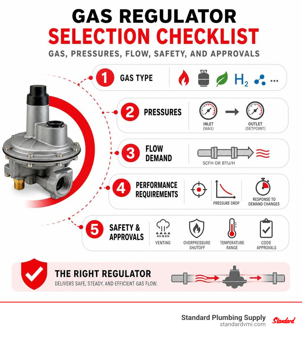
A gas pressure regulator reduces incoming gas pressure and holds the outlet near a safe setpoint as supply pressure and equipment demand change. To choose the right one, confirm these five items first:
- Gas type: natural gas, propane, biomethane, hydrogen blend, or another approved gas.
- Maximum inlet pressure and required outlet pressure.
- Peak flow demand, usually measured in SCFH or Btu/h.
- Required accuracy, allowable pressure drop, and whether demand changes quickly.
- Safety and installation needs, including venting, overpressure shutoff, temperature range, and code approvals.
The wrong regulator can cause weak burner performance, pressure creep, nuisance shutdowns, or damage to downstream equipment. Spring-loaded models are often the practical, economical choice for smaller loads, while pilot-operated regulators are better suited to high-flow or high-accuracy work such as district stations, large boilers, and turbine fuel trains.
For property managers and small business owners, good selection also means choosing a unit your team can service and replace without long downtime. Standard Plumbing Supply helps HVAC and plumbing professionals source trusted gas-control products with expert support, fast nationwide shipping, and inventory solutions that make planned maintenance easier.
I am Jacob Reese, Vice President at Standard Plumbing Supply, with experience supporting contractors and facilities teams through product selection, supply planning, and dependable distribution. In this guide, I will help you evaluate the gas pressure regulator details that matter before you order, install, or replace one.
Operating Principles and Key Mechanical Components
To understand why a regulator performs well or fails under shifting loads, we need to look inside the housing. A standard gas pressure regulator operates completely mechanically without requiring external electrical power. It is a self-contained, modulating throttling device designed to maintain force equilibrium between downstream gas pressure and a mechanical loading element.
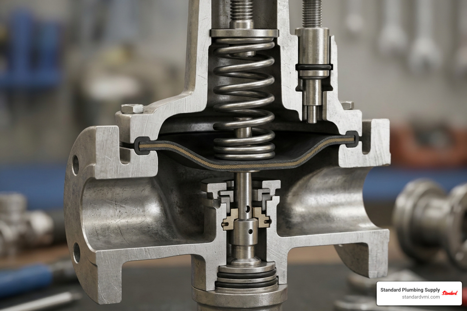
Every regulator relies on three essential elements:
- The Loading Element (Range Spring): Provides the mechanical reference force that sets downstream delivery pressure.
- The Measuring Element (Diaphragm or Piston): Senses downstream pressure changes and converts pressure into mechanical force opposing the loading spring.
- The Restricting Element (Valve Plug / Poppet and Orifice Seat): Opens or closes the flow path between the high-pressure inlet and low-pressure outlet.
When atmospheric venting is present, the top of the diaphragm references ambient atmospheric pressure. In higher-capacity or specialized systems, an impulse line (sensing line) taps downstream pipe pressure directly back to the lower diaphragm chamber, bypassing internal turbulence for clean feedback.
Force Balance and Step-by-Step Operation
The operation of a direct-acting regulator follows a continuous, dynamic force balance loop across the diaphragm:
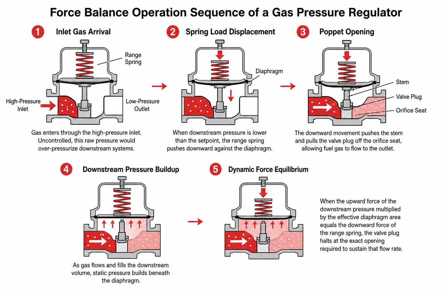
- Inlet Gas Arrival: Gas enters through the high-pressure inlet. Uncontrolled, this raw pressure would over-pressurize burner manifolds or downstream piping.
- Spring Load Displacement: When downstream pressure is lower than the setpoint (such as when a boiler fires up), the range spring pushes downward against the diaphragm plate.
- Poppet Opening: The downward movement pushes the stem and pulls the valve plug off the orifice seat, allowing fuel gas to flow into the outlet piping.
- Downstream Pressure Buildup: As gas fills the downstream volume, static pressure builds beneath the flexible diaphragm.
- Dynamic Force Equilibrium: When the upward force of the downstream pressure multiplied by the effective diaphragm area equals the downward force of the range spring, the valve plug halts at the exact opening required to sustain that flow rate.
- Droop and Lockup: When equipment shuts off, flow drops to zero. Downstream pressure rises slightly above setpoint to drive the plug tightly into the soft elastomeric seat—a threshold known as lockup pressure. Conversely, as flow surges to maximum capacity, spring extension causes a slight reduction in delivery pressure known as droop.
For detailed historical and engineering context on flow systems across energy networks, technical resources like the Energy Resource Dev. Systems Report Vol. II outline the mechanical baseline of modern fluid and gas dynamics.
Critical Internal Components and Construction Materials
Selecting the proper materials ensures safety, structural integrity, and long service life:
- Regulator Body: Typically constructed from die-cast aluminum (for residential and light commercial units up to 10–125 psig inlet), ductile iron, or cast steel (for industrial utility lines and high-pressure transmission up to 150–5,500 psig).
- Diaphragms: Molded Nitrile (NBR) or rubberized fabric diaphragms offer excellent chemical resistance to hydrocarbons, low hysteresis, and flexibility across ambient working temperatures from -40 °F to +140 °F (-40 °C to +60 °C). Fluoroelastomer (FKM) diaphragms are used in high-temperature or aggressive hydrocarbon applications.
- Valve Seats and Seals: Elastomers such as NBR, Buna-N, PTFE, or Nylon poppet discs ensure bubble-tight shutoff (ANSI/FCI 70-3 Class VIII equivalent or better) at zero flow.
- Trim and Fasteners: Stainless steel stems, linkages, and internal springs resist rust and galvanic corrosion. When installing stainless steel instrumentation lines and pilot sensing tubes, contractors often rely on durable compression components like the Apollo SmartPress Fitting to ensure leak-free impulse and vent piping.
Primary Categories of the Gas Pressure Regulator
Not all gas loads behave the same way. Regulators are engineered into distinct structural categories to handle everything from small kitchen appliances to high-pressure city gate stations.
| Regulator Category | Pressure Handling | Flow Capacity | Typical Accuracy Class | Best Applications |
|---|---|---|---|---|
| Direct-Operated (Spring-Loaded) | Inlet up to 125–150 psi | Low to Moderate (up to ~20,000 SCFH) | AC 5 to AC 10 (Moderate droop) | Residential meters, commercial rooftop units, unit heaters, line pressure reduction |
| Pilot-Operated | Inlet up to 1,500+ psi | Very High (up to hundreds of thousands SCFH) | AC 1 to AC 2.5 (Tight +/-1% control) | City gate stations, district regulating stations, large industrial boiler plants |
| Single-Stage | Inlet up to 10–125 psi | System dependent | Standard | Steady inlet supplies, intermediate appliance manifold lines |
| Dual-Stage (Two-Stage) | High cylinder or tank inlet (up to 3,000+ psi) | Stable across broad flow ranges | High stability against inlet swings | High-pressure propane bulk tanks, laboratory gas systems, primary utility drops |
Direct-Acting vs. Pilot-Operated Mechanisms
Direct-acting regulators are the industry workhorses. The diaphragm directly actuates the valve stem. Because they have few moving parts and no auxiliary controls, they respond instantly to load shifts and represent an economical choice for commercial buildings, unit heaters, and furnaces.
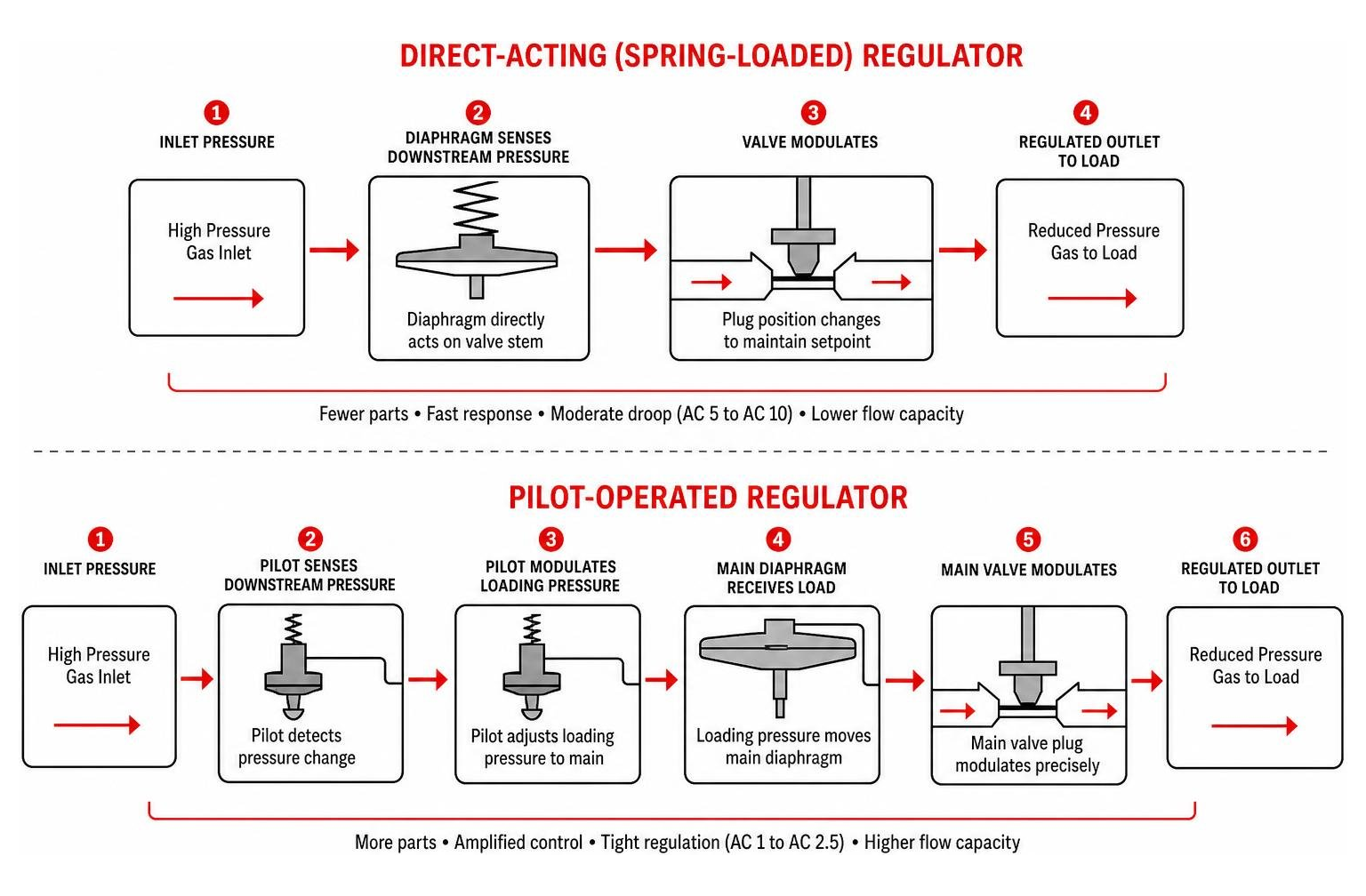
When flow demands are massive or allowable outlet droop is narrow (such as +/-1% absolute pressure for billing or combustion burner stability), a pilot-operated regulator is required. Pilot-operated systems use an auxiliary pilot regulator to sense downstream pressure and amplify small changes. The pilot modulates loading pressure onto a larger main diaphragm or boot, driving heavy plugs with pinpoint accuracy across variable inlet conditions. Advanced designs from specialized manufacturers of Natural Gas Pressure Regulators provide tight process control on gas turbine feeds and industrial heating processes.
Single-Stage vs. Two-Stage Pressure Reduction
Industrial gas cylinders often store gas at 3,000 psi or more, and bulk propane tanks experience wide pressure swings with outdoor temperature shifts.
When upstream supply pressure fluctuates significantly, single-stage regulators experience the supply pressure effect (inlet pressure sensitivity)—as inlet pressure drops, outlet pressure may drift upward.
A two-stage reduction setup solves this:
- First Stage: Cuts raw tank or pipeline pressure (e.g., dropping 100–250 psi down to an intermediate 5–10 psi).
- Second Stage: Drops intermediate pressure down to appliance-level inches of water column (in. w.c., such as 7" w.c. for natural gas or 11" w.c. for LP).
For isolation between stages or servicing lines safely, using an approved quarter-turn shutoff such as a Jomar Gas Ball Valve upstream ensures clean isolation during routine maintenance and startup.
Sizing and Engineering Selection Criteria
A common field mistake is sizing a regulator based entirely on pipe nominal diameter (e.g., matching a 2" line to a 2" regulator). Oversizing a regulator causes high-velocity seat chatter, premature wear, and unstable hunting, while undersizing starves downstream burners during peak cold mornings.
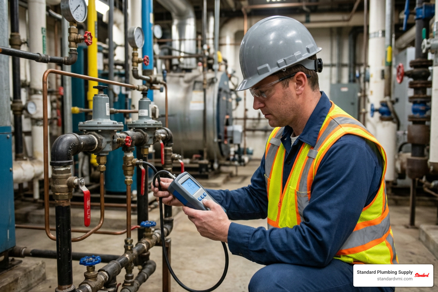
Sizing a Gas Pressure Regulator by Flow and Pressure Drops
To size a regulator accurately, calculate the required flow coefficient ($K_G$) based on the operating pressure conditions.
The sizing calculation changes depending on whether flow through the orifice is subcritical or supercritical:
-
Supercritical Flow (when downstream absolute pressure is less than or equal to half the inlet absolute pressure: $\frac{Pd}{Pu} \le 0.5$): $$KG = \frac{2 \cdot Qn}{P_u}$$
-
Subcritical Flow (when downstream absolute pressure is greater than half the inlet absolute pressure: $\frac{Pd}{Pu} > 0.5$): $$KG = \frac{Qn}{\sqrt{Pd \cdot (Pu - P_d)}}$$
Where:
- $Q_n$ = Standard flow rate in $\text{Nm}^3/\text{h}$ (or converted to SCFH)
- $P_u$ = Absolute inlet pressure ($\text{bar}_a$ or $\text{psia}$)
- $P_d$ = Absolute outlet setpoint pressure ($\text{bar}_a$ or $\text{psia}$)
When sizing spring-loaded devices, always include a 10% to 20% capacity reserve margin above peak calculated demand.
Additionally, verify line gas velocities to minimize pipe erosion and acoustic noise:
- Inlet Flange Gas Velocity: Maintain between $50 \text{ m/s}$ and $70 \text{ m/s}$ ($20\text{--}30 \text{ m/s}$ directly upstream of filters).
- Outlet Flange Gas Velocity: Keep within $100 \text{ m/s}$ to $200 \text{ m/s}$. If velocities exceed this limit due to downstream expansion, expand downstream piping diameter directly at the regulator outlet.
- Impulse Line Tap Velocity: Keep below $15\text{--}25 \text{ m/s}$ to prevent dynamic pressure distortion at the sensing diaphragm.
Fuel Compatibility and Environmental Certifications
Gas distribution equipment must align with local mechanical codes and specific fuel compositions:
- Hydrogen Blending and Biomethane: As utilities adopt decarbonization targets in 2026, modern line regulators like the FE series handle biomethane and natural gas blended with up to 20% hydrogen without seal degradation. For hydrogen calculations, a gas correction factor of $3.04$ is applied against natural gas baseline flow.
-
Industry Standards:
- ANSI Z21.80 / CSA 6.22: North American standard for line pressure regulators up to 2, 5, or 10 psig systems.
- ANSI B109.4: Applies to service regulators for natural gas utilities.
- EN 334 / EN 88 / EN 13611: European directives governing gas pressure regulators and safety shutoff devices.
- Corrosive Environments: For outdoor installations near coastal regions or industrial chemical exposure, look for epoxy resin coatings qualified for C5-M corrosivity categories.
Safety Systems, Maintenance, and Troubleshooting
Gas lines require integrated fail-safe mechanisms to prevent overpressurization of downstream piping in the event of foreign debris lodging in the valve seat.
Integrated safety mechanisms include:
- Overpressure Shut-Off (OPSO): An internal or slam-shut valve that snaps closed automatically if outlet pressure rises beyond a safe trip threshold (e.g., 140% of nominal setpoint). It requires manual reset once line integrity is restored.
- Underpressure Shut-Off (UPSO): Trips closed if supply line pressure collapses, preventing unburned gas leakage when supply is suddenly restored.
- Internal Relief Valves (IRV): A spring-loaded relief vent in the diaphragm assembly that safely bleeds low-volume excess pressure out the atmospheric vent during minor lockup creep.
- Vent Limiters: Small ball-check assemblies mounted in the atmospheric vent boss that permit normal breathing during operation but restrict gas discharge to negligible levels (under $30 \text{ l/h}$ or ANSI Z21.80 limits) if the main diaphragm ruptures, eliminating the need for expensive exterior vent piping on approved indoor installations.
How to Adjust and Maintain a Gas Pressure Regulator
Regular maintenance keeps critical pressure controls functioning within spec:
- Adjusting Setpoint: Remove the protective seal cap. To increase outlet pressure, turn the adjustment screw clockwise (compressing the range spring). To decrease outlet pressure, turn the screw counter-clockwise. Always monitor downstream pressure using a calibrated digital manometer while adjusting.
- Spring Range Swapping: If required outlet pressure falls outside the stamped range of the existing spring, isolate the regulator, relieve line pressure completely, remove the spring dome, and install the appropriate color-coded spring.
- Upstream Filtration: Always install a sediment trap (drip leg) or 40-to-50 micron gas filter upstream. When servicing burner combustion controls and analyzer loops, utilizing components like the FB1 Chemical Filter Bypass protects sensitive testing instruments from particulate fouling.
- Bubble-Tight Seat Testing: Annually test lockup tightness. Close downstream valves and observe gauge pressure. A minor rise (10–20% above setpoint) followed by a solid hold indicates proper lockup. Continuous pressure climb signals seat leakage.
Diagnosing Regulator Creep, Chatter, and Lockup Failure
When troubleshooting a regulator in the field, use this diagnostic framework:
-
Issue: Pressure Creep (Outlet Pressure Slowly Climbs at Zero Flow)
- Root Cause: Debris (pipe scale, welding slag, thread sealant) lodged between the elastomeric valve seat and the orifice knife-edge, or a scored seat disc.
- Fix: Isolate the line, clean internal trim, or replace the soft seat insert.
-
Issue: High-Pitched Squeal or Valve Chatter
- Root Cause: Severe oversizing or the regulator being installed too close to an elbow or quick-closing solenoid valve, causing turbulent feedback.
- Fix: Downsize orifice diameter, install acoustic dampening/insulation, or relocate impulse lines at least 5 pipe diameters downstream of turbulence sources.
-
Issue: Freezing or Icing on Regulator Body
- Root Cause: The Joule-Thomson effect causes gas temperatures to drop rapidly across large pressure drops (approx. $1^\circ\text{F}$ drop per $15\text{--}20\text{ psi}$ pressure reduction). High moisture content in wet gas can form ice hydrates inside the throat.
- Fix: Install upstream line preheaters, use dual-stage staged drops, or install a heated enclosure.
Frequently Asked Questions About Pressure Control
What causes a regulator to vent gas continuously?
Continuous venting from the atmospheric vent port usually points to one of two critical failures:
- Ruptured Diaphragm: The internal measuring diaphragm has developed a tear or hole, allowing pressurized gas from the lower chamber to escape into the upper spring dome and out the vent.
- Internal Relief Activation: The valve seat is compromised, creating an overpressure condition downstream that opens the internal relief valve to protect downstream equipment.
In either scenario, the regulator must be isolated immediately and serviced or replaced.
How often should line regulators be serviced or replaced?
Standard industrial and commercial gas line regulators (such as those adhering to EN 13611 and EN 88) are engineered with a designed lifetime of 15 years under clean natural gas service.
However, best practices require annual visual inspections, leak checks, and lockup tests. For aggressive, corrosive fuels like untreated biogas or landfill methane containing hydrogen sulfide ($H_2S$), inspection intervals should be reduced to every six months.
What is the difference between lockup pressure and droop?
- Lockup Pressure: The static downstream pressure measured when burner valves shut completely and flow stops. Because mechanical force is required to compress the soft seat against the metal orifice, lockup pressure is slightly higher than the dynamic flowing setpoint (typically 0.5" to 2" w.c. higher).
- Droop: The drop in downstream delivery pressure experienced as flow demand increases from low fire to full burner load. Droop is caused by spring relaxation as the spring extends to push the valve plug wider open.
Conclusion
Selecting the right gas pressure regulator ensures system safety, peak combustion efficiency, and code compliance across your facilities. Matching your required inlet range, outlet setpoint, peak SCFH flow rate, and safety shutoff features protects downstream boilers, furnaces, and commercial appliances from costly downtime.
Standard Plumbing Supply supports plumbing, HVAC, and mechanical contractors across Utah, Idaho, Wyoming, Colorado, Nevada, California, Arizona, Oregon, and Nebraska. Through our extensive branch network and centralized distribution, we provide:
- Full access to commercial gas controls and certified pressure relief valves.
- Technical sizing support from experienced product specialists.
- Fast nationwide shipping to keep job sites on schedule.
- Customizable Vendor-Managed Inventory (VMI) programs that reduce stockouts, streamline shop inventory, and improve cash flow.
Visit your nearest Standard Plumbing Supply branch or connect with our technical sales team today to configure dependable gas control and pressure regulation solutions for your next project.