
Detailed Guide to Selecting the Correct Pressure Relief Valve Type
Learn how to select the correct pressure relief valve for your system with this guide on types, sizing, and installation best practices.

Why Choosing the Right Pressure Relief Valve Matters
A pressure relief valve is a safety device that opens when system pressure rises above its set limit. It releases water, steam, gas, or other fluid to prevent damage to pipes, pumps, tanks, boilers, and connected equipment.
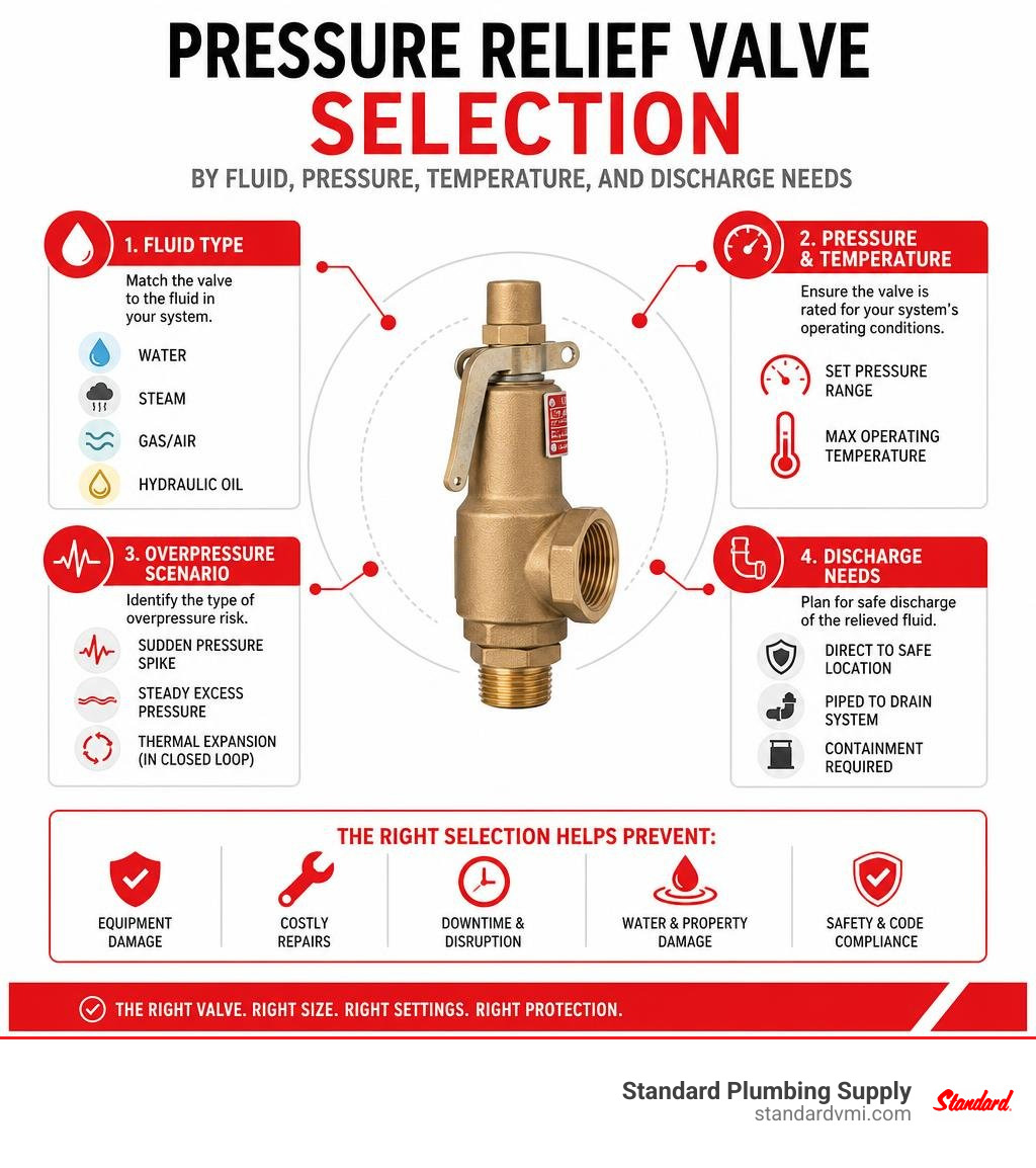
Choosing the correct type starts with four questions:
- What fluid is in the system: water, steam, gas, or hydraulic oil?
- What pressure and temperature must the valve handle?
- Is the risk a sudden pressure spike, steady excess pressure, or thermal expansion in a closed loop?
- Where will discharged fluid go safely?
A valve that is too small, set incorrectly, or incompatible with the fluid can leak, chatter, fail to open when needed, or discharge too often. For property managers and small business owners, the right selection helps avoid downtime, water damage, emergency repairs, and costly equipment loss.
This guide breaks down the major valve types for plumbing, HVAC, irrigation, and process applications, along with the practical selection factors that matter when ordering parts or planning maintenance. Standard Plumbing Supply supports contractors and facility teams with reliable product availability, fast nationwide shipping, and knowledgeable help for keeping critical systems protected.
I am Jacob Reese, Vice President at Standard Plumbing Supply, with experience supporting plumbing and HVAC contractors through product selection, inventory planning, and urgent repair needs. In the next sections, I will help you identify the pressure relief valve design that fits your system and avoids common selection mistakes.
Understanding Pressure Relief Valve Functions and Mechanics
At its core, a Relief valve is an automated fail-safe designed to prevent catastrophic overpressurization. Whether installed on a municipal water booster system, a high-rise hydronic heating loop, or a commercial hot water storage tank, the basic mechanical principle relies on a balance of forces.
Inside the valve body, an internal disc or plug is held securely against a precision-machined seat by a pre-loaded mechanical spring or diaphragm assembly. During normal operating conditions, the force exerted by the system fluid against the exposed surface area of the disc is lower than the downward mechanical force exerted by the spring. This maintains a leak-tight seal.
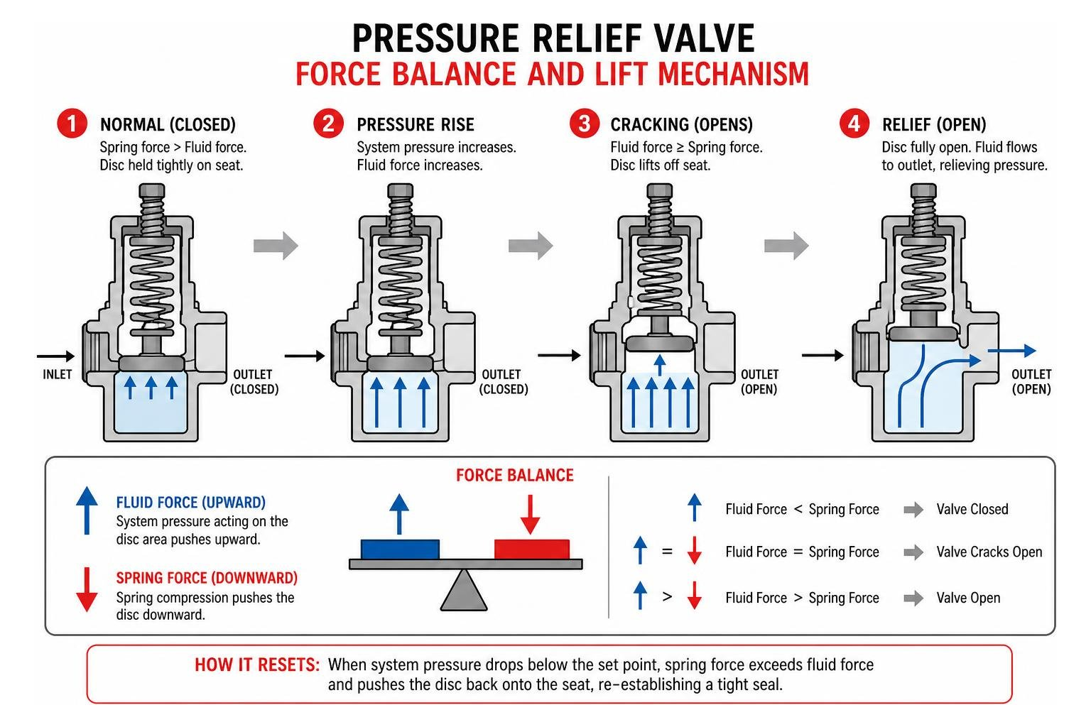
When abnormal operating conditions occur—such as thermal expansion, a closed downstream valve, or pump runaway—the upstream fluid pressure rises. Once this pressure reaches the predetermined cracking threshold, the fluid force overcomes the internal spring compression. The disc lifts off its seat, creating a dedicated discharge path for fluid, gas, or steam to escape. This action relieves excess hydraulic or pneumatic force before piping walls rupture, boiler vessels burst, or downstream components fail. Once system pressure safely normalizes, the spring forces the disc back onto the seat to re-establish a complete seal.
Direct Spring vs Pilot-Operated Pressure Relief Valve Designs
Direct spring-operated valves and pilot-operated relief valves represent the two primary engineering frameworks used across mechanical and plumbing systems.
- Direct Spring-Operated Valves: The simplest and most widely deployed design. In this setup, the process fluid pushes directly against the seating disc, which is opposed by a heavy mechanical coil spring. Direct-acting valves are dependable, fast-reacting, and ideal for standard domestic hot water, hydronic balance loops, and smaller commercial applications. However, because the spring force increases as it compresses, direct-acting valves require a noticeable pressure rise above the setpoint to achieve full flow lift.
- Pilot-Operated Valves: These assemblies utilize a two-stage mechanism consisting of a main valve (featuring a piston, spool, or flexible diaphragm) and a smaller, highly sensitive pilot control valve. Upstream process fluid is routed into a dome chamber above the main closing element, keeping it seated tightly via system pressure itself. When set pressure is reached, the external pilot vents the dome fluid, allowing the main valve to pop open completely and instantaneously. Pilot-operated valves excel in high-flow, high-pressure, or tight-tolerance industrial scenarios where seat leakage near the setpoint cannot be tolerated.
| Feature | Direct Spring-Operated | Pilot-Operated | Thermal Relief Valve |
|---|---|---|---|
| Primary Media | Liquid, Gas, Steam | Clean Gas, Liquids, Hydraulics | Incompressible Liquids (Water/Glycol) |
| Operating Pressure | Low to Very High (up to 600+ bar) | Medium to Ultra-High (up to 350+ bar) | Standard Plumbing (50–150 PSI) |
| Lift Profile | Proportional / Modulating | Instantaneous / Full Lift | Micro-Discharge / Droplet Bleed |
| Tolerance to Backpressure | Moderate (Alters Setpoint 1:1) | High (Independent with External Vent) | High |
| Primary Maintenance | Mechanical Spring & Seat Inspection | Pilot Orifice & Diaphragm Cleaning | Seat Descaling & Elastomer Check |
| Best Use Case | Boilers, Water Heaters, Hydronics | Large Gas Mains, High-Flow Hydronics | Closed Plumbing Loops, Solar Thermal |
Key Operating Terminology: Set Pressure, Overpressure, and Blowdown
Understanding standard relief valve terminology ensures that you specify equipment accurately to meet ASME and local plumbing code mandates:
- Set Pressure (Cracking Pressure): The exact inlet gauge pressure at which the valve begins to open and measurable fluid discharge starts.
- Overpressure: The pressure increase above the setpoint necessary for the valve to achieve its full design discharge flow rate (typically 3% to 10% above set pressure depending on ASME vessel standards).
- Reseating Pressure: The reduced system pressure level at which the valve disc firmly contacts the seat again, halting all discharge.
- Blowdown: The numerical difference between the set pressure and the actual reseating pressure, expressed as a percentage of set pressure. Blowdown typically ranges between 2% and 20%. Proper blowdown prevents the valve from "hunting" or chattering rapidly against the seat.
- Modulating Action vs. Snap-Acting Lift: Modulating valves open gradually in direct proportion to the pressure increase—ideal for incompressible liquids. Snap-acting valves utilize an aerodynamic disc skirt to catch escaping vapor, popping wide open in milliseconds—standard for compressible gases and steam.
- Backpressure Effects: Superimposed or built-up counter-pressure in the discharge piping that opposes the valve opening. In standard direct-acting valves, backpressure adds 1:1 to the required cracking pressure unless a balanced bellows or balanced diaphragm design is utilized.
Primary Classifications of Relief and Regulating Valves
Selecting the correct device requires matching valve geometry and actuation mechanics to the specific fluid dynamics of your facility.
Safety Relief Valves for Gas and Steam Service
Vapor service carries immense stored kinetic energy. When steam boilers or compressed air receivers exceed safe operating limits, the relief device must dump vast volumes of expanded gas instantaneously.
Safety relief valves engineered for steam and air service feature specialized pop-action skirts and ASME Section I or Section VIII certifications. They incorporate emergency manual test levers, allowing technicians to verify free stem movement and blow clear minor seat deposits during quarterly inspections. Because steam discharge can produce intense acoustic decompression shockwaves, these valves often integrate specialized damping chambers to prevent structural fatigue.
Pressure Regulating and Direct-Acting Water Pressure Valves
In potable water distribution and closed-loop hydronic networks, excess pressure is often a chronic municipal supply issue rather than an instantaneous emergency spike. High municipal incoming pressure causes premature appliance failure, fixture leaks, and severe pipe stresses.

To regulate incoming city water, contractors install direct-acting pressure reducing and regulating valves. For standard residential branch lines, a PRV 3/4 Sweat provides dependable downstream reduction, stepping line pressure down from 100+ PSI to a steady 50 PSI. For larger residential estates or light commercial buildings requiring union connections and easy cartridge maintenance, the 1 in. NR3XL Double Union Sweat PRV provides exceptional flow management. In high-demand commercial loops or heavy multi-family structures, a high-capacity 1-1/4 in. 25AUB-S-Z3 SU Sweat PRV ensures smooth bypass flow without restricting peak volume.
Thermal Expansion and Vacuum Relief Assemblies
When water is heated inside a closed system containing a backflow preventer or check valve, it expands hydrostatically. Because water is non-compressible, a temperature rise from 50°F to 140°F within an unvented 50-gallon tank can drive domestic pressure past 150 PSI, causing relief discharge or tank rupture.
Dedicated thermal expansion valves protect residential and light commercial Water Heating & Treatment equipment by venting tiny, controlled volumes of fluid during the heating cycle to maintain balanced pressure.
Conversely, systems can also suffer structural collapse from internal negative pressure (vacuum). Rapid vessel draining, steam condensation, or sudden supply line drops can implode thin-walled storage vessels and irrigation lines. To protect outdoor irrigation circuits and prevent dangerous backsiphonage, installing an assembly like the 1 in. 800M4-QT Freeze Resistant Pressure Vacuum Breaker admits atmospheric air when positive pressure drops, protecting both piping integrity and municipal potable water purity.
Sizing and Selection Criteria for Commercial and Residential Systems
Improper valve sizing remains the leading cause of field failures. An oversized relief valve will open, dump pressure too rapidly, slam shut, and cycle repeatedly (chatter), destroying its internal seat faces in minutes. An undersized valve will fail to discharge volume fast enough during a thermal runaway, allowing line pressure to climb past vessel burst limits.
Sizing Your Pressure Relief Valve for Temperature and Flow Demands
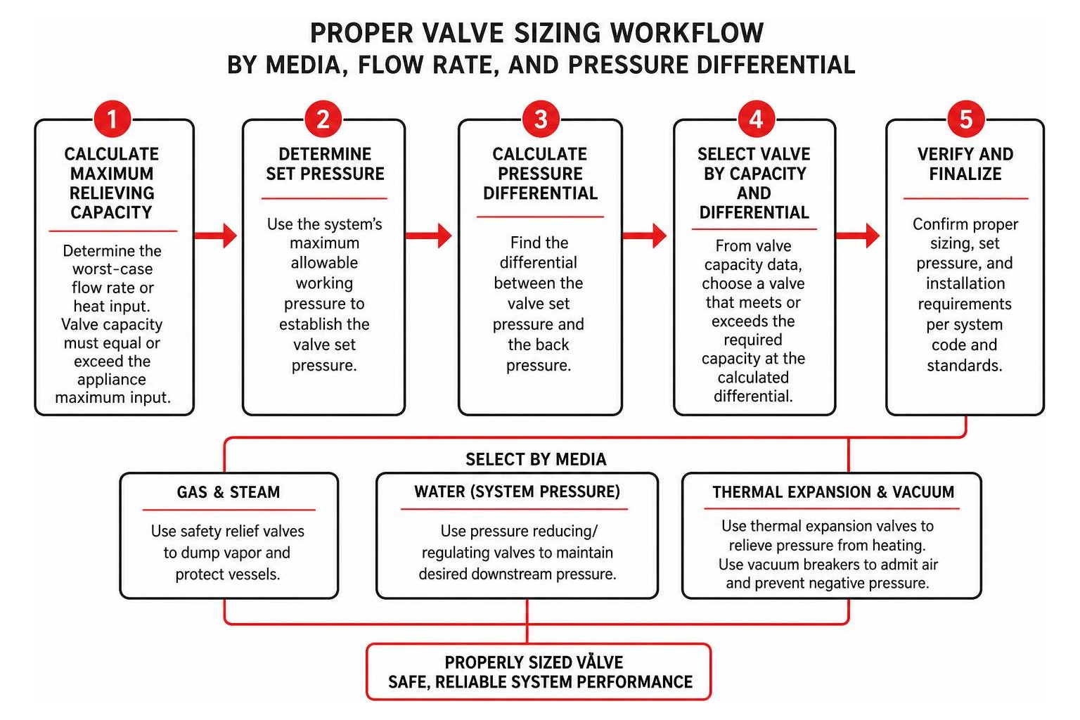
Proper sizing follows five sequential calculations:
- Calculate Maximum Relieving Capacity: Determine the worst-case volumetric flow rate or heat input generation. For water heaters and boilers, the valve's rated relieving capacity (stamped in BTU/hr or lbs/hr of steam) must equal or exceed the maximum burner or element input rating of the appliance.
- Determine Orifice Area: For liquid or process flow, use the standard flow equation: $$Q = C_v \sqrt{\frac{\Delta P}{G}}$$ Ensure the internal orifice size satisfies total pump discharge capacity at allowable overpressure limits.
-
Account for Temperature Ranges and Seal Elastomers: Match the internal elastomer trim to fluid conditions:
- Nitrile (NBR): Ideal for standard water, hydronics, and mineral oils (-20°F to +200°F).
- Fluoroelastomer (FKM / Viton): Required for high-temperature water, glycol, synthetic oils, and mild chemicals (-15°F to +400°F).
- EPDM: Best for high-temperature potable water, steam cleaning, and caustic washdowns.
- Evaluate Upstream/Downstream Piping Diameters: The inlet piping leading to a relief valve must never be smaller in diameter than the valve inlet connection itself. Friction loss in upstream piping should not exceed 3% of the valve's set pressure to prevent valve chatter.
Application Matching: Plumbing, HVAC, and Industrial Process Loops
Every building environment demands specific metallurgy, cleanability, and pressure response characteristics:
- Potable Domestic Water: Lead-free bronze or brass bodies with NSF/ANSI 61 and 372 certifications.
- Commercial HVAC & Hydronic Heating: Cast iron or bronze valves calibrated to ASME Section IV rules (standard 30 PSI relief for low-pressure hydronics, up to 125 PSI for high-rise chilled water loops).
- Hygienic Food, Dairy, and Beverage: Heavy-duty stainless steel (AISI 316L / EN 1.4404) with surface roughness ratings below Ra 0.8 μm. These applications, such as those utilizing an Alfa Laval Pressure Relief Valve, incorporate clean-in-place (CIP) pneumatic seat lifters and dedicated splash guards to allow sanitizing chemical flushes across the seat.
- Industrial Hydraulics: Solid carbon steel or plated ductile iron cartridge valves capable of withstanding operating pressures up to 350 to 630 bar with specialized damping orifices to eliminate hydraulic shock.
Industry Codes, Standards, and Best Installation Practices
Pressure relief devices are strictly regulated life-safety equipment. Installations must comply with relevant regional and national engineering standards:
- ASME Section I: Governs fired pressure vessels and power steam boilers (requires strict 3% overpressure capacity limits).
- ASME Section IV: Governs low-pressure heating and hot water supply boilers.
- ASME Section VIII: Applies to unfired industrial pressure vessels and liquid accumulators.
- API 520 / 526: Establishes sizing, selection, and dimensional flange criteria for refinery and petrochemical process loops.
- Uniform Plumbing Code (UPC) & International Plumbing Code (IPC): Mandates temperature and pressure (T&P) relief valves on all storage water heaters, set at a maximum of 150 PSI and 210°F.
When piping a relief device into service, observe these universal installation rules:
- No Isolation Upstream of Safety Relief: Never install shutoff valves between the pressure source and an ASME safety relief valve. For non-code maintenance setups requiring isolation, always install full-port lockable Ball Valves equipped with approved mechanical interlocks or three-way selector valves to prevent accidental isolation during operation.
- Independent Discharge Pipe Sizing: Discharge lines must match or exceed the outlet port size, pitch downward toward an approved floor drain, and terminate between 6 to 24 inches above the floor with an unthreaded end.
- Eliminate Trapped Condensate: Avoid upward piping runs on discharge lines. If vertical discharge runs are unavoidable, install a low-point drain port at the valve elbow to prevent trapped water from freezing or putting hydrostatic head backpressure onto the disc.
Maintenance, Inspection, and Troubleshooting Common Failures
A neglected relief valve can freeze shut from mineral encrustation or weep continuously, creating massive water waste and safety risks.
- Seat Weeping and Dripping: The most common field complaint. Often caused by tiny pieces of sediment, solder flux, or calcium scale trapped between the soft seal and the metal seat. Manually lifting the test lever for 5 seconds to flush line debris often clears the seat. If weeping continues, thermal expansion without an expansion tank or a failed internal rubber seal is the root cause.
- Valve Chattering: Rapid, violent opening and closing. Caused by an oversized valve, excessive pressure drop in long upstream inlet piping, or high backpressure in the discharge line. Left unaddressed, chattering causes fatigue cracking in internal springs and destroys the precision seat.
- Mineral Scale & Corrosion Seizure: In hard water areas across Utah, Nevada, and Arizona, calcium carbonate coats internal springs and stems, locking the disc in place.
All commercial and residential safety relief valves should undergo manual trip lever testing annually and full replacement every 3 to 5 years depending on local water chemistry and operating duty.
Frequently Asked Questions About Pressure Relief Valves
What is the difference between a PRV and a PSV?
While terms are often used interchangeably on job sites, a Pressure Relief Valve (PRV) is primarily used for liquid fluid service, opening proportionally as pressure increases. A Pressure Safety Valve (PSV) is designed for compressible gases and steam, featuring an emergency manual lift lever and an internal pop-action disc skirt that snaps wide open in milliseconds to vent volatile pressure instantly.
Why is my relief valve constantly dripping or weeping?
A dripping relief valve typically points to one of three issues:
- Thermal expansion in a closed plumbing loop lacking an expansion tank.
- Incoming municipal supply pressure exceeding the valve's cracking setpoint.
- Mineral scale or debris lodged directly under the elastomer seal face.
Flushing the valve via the manual test lever or installing an expansion tank on the cold water inlet will resolve most domestic weeping issues.
How often should relief valves be tested and replaced?
ASME and national plumbing codes recommend manually checking safety relief valves once per year by operating the test lever to ensure free water passage. In commercial and industrial facilities, relief devices should be bench-tested and recalibrated every 1 to 3 years. Complete replacement is standard practice every 4 to 5 years to safeguard against invisible spring fatigue and elastomer degradation.
Conclusion
Selecting the correct pressure relief valve requires balancing system media, operating pressures, temperature envelopes, and flow dynamics. Whether you are balancing hydronic heating lines, outfitting a municipal pump station, or installing domestic water heaters, choosing high-performance, code-certified equipment protects your property and eliminates costly emergency shutdowns.
At Standard Plumbing Supply, we pair top-tier products from trusted manufacturers with deep technical knowledge across our locations in Utah, Idaho, Wyoming, Nevada, Arizona, California, Oregon, Colorado, and Nebraska. With our robust vendor-managed inventory (VMI) services and fast nationwide shipping, we help contractors and facilities maintain immediate access to the exact valves, fittings, and diagnostic tools they need.
For additional technical field checks and routine system maintenance tips, explore our guide on compression gauge and Schrader valve maintenance to keep all your pressure diagnostic equipment operating at peak accuracy.